Knowing about how a computer is made is one of the most interesting to me. I find it interesting as I am someone who is interested in what is going on in a system, whether a computer or another machine. This blog is an attempt to explain what a computer is. By 'what a computer is,' I mean how a computer is built and what the components and architecture of a computer are. It is also an attempt to simplify computer system which is a course taken by CS student. This does not mean it is only for CS student rather it is also for anyone interested in having an understanding how a computer is made and it architecture. I will also ensure to use simple language as possible and explain all the technical terms if there is a need to use one.
A computer is a black box of very big abstraction. One thing you should understand is that the computer we use mostly is built on electronics concepts like voltage and the transistor(some few computers are exemption but, generally our laptops, desktops etc uses electronics). But the question is how? Let's go.
Computers operate on binary system which is basically 0's and 1's. With the help of transistors which are powerfully electronic devices we can represent 0's and 1's. Transistors can act as a switch as It can either allow current to pass through or not. When it allow current to pass through, we can represent it as 1 and when it does not allow current to pass through it, we can represent it as 0.

The above picture represent a P-mosfet(a type of transistor). When the Gate is 1 i.e voltage is applied to the gate terminal the bulb will turn on and if is 0 i.e no voltage is applied at the gate terminal the bulb will be off. We can basically take advantage of this and represent 1 as when the bulb is on and represent 0 as when the bulb is off. That is basically the idea, since we are not studying physics we will not go deeper than this.
Logic Gates.
The question now is that, how is the above representation useful ? this is exactly were the logic gates comes in. Computers are, in fact, built on logic gates which basically contain one or more transistors.
Let's take a look at the NAND Gate which basically contains four transistors with two inputs through the base and also one output. The input basically accepts voltage and the output is also voltage. If the two voltages are off(both are one) and we place a bulb at the output, it will light up(output will be 1). If they are both one the output will 0.
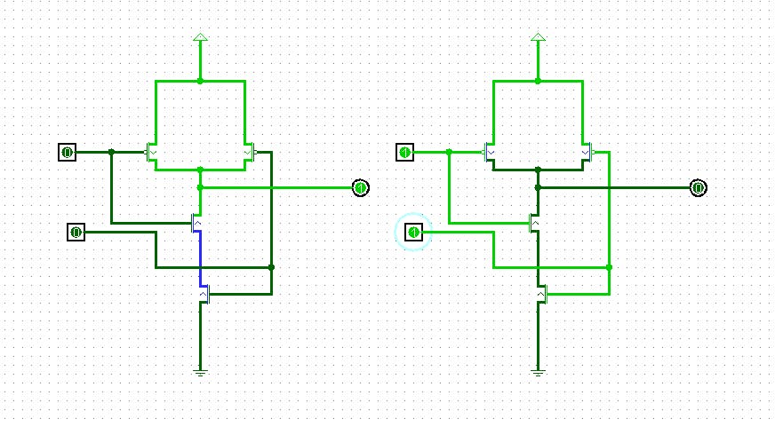
Before moving on, if you know the binary system (not compulsory), whenever we have two inputs (bits - a bit is either 0 or 1), we can have four possible combinations. For the above, we can have (0,0), (0,1), (1,0), (1,1). For a NAND gate, all combinations will give 1 except (1,1). This aspect in the computer system is known as a truth table under the combinatorial circuit.
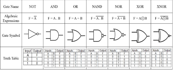
This is the starting point of everything. It is now possible for us to use a transistor and voltage to make a logic gate and represent 1 or 0. There are a lot of logic gates out there. I only mentioned NAND; there are also OR, NOT, AND, XOR, etc. The NAND gate is called the universal logic gate, which simply means all other gates can be derived from this gate.
Below is the abstract representation (without showing the transistors they are made of) of the logic gate, the truth tables, and symbols.
"Now, let's delve into the power of the logic gate and how we can use it to add numbers. I will provide an overview of the addition of two bits (note that it is in the binary system; the default number we use is in decimal, i.e., base ten, but can be converted to the base two or binary system and vice versa). Two bits are added together with a carry bit from the previous lower-order operation.
Using logic gates, a half-adder combines two bits to produce a sum (XOR gate) and a carry (AND gate). The sum represents the result, while the carry indicates overflow, which is crucial in multi-bit addition for accurate calculations in digital systems. In some parts of the world, the carry is known as a remainder."

There is also a full adder, which gives us the capability to add multiple bits together as it takes into consideration the carry from the previous addition. With this, we have been able to move from transistors to the addition of bits. Subtraction involves the conversion of a number to its 2's complement. For example, in an operation A - B, B will be converted to its equivalent 2's complement, and then A and B will be added together.
Using similar methods, operators like bit-shifting operators can be created. Through a series of other processes, we can have a system that can add, subtract, divide, and multiply more than just a single bit together using an array.
Below is the image of a 4-bit adder; it can add two 4-bit numbers together, for example, 1100 + 0001.

The next thing is a multiplexer, which is basically a device made of transistors that can allow us to select a certain output through some select lines. Its opposite is what we know as a demultiplexer.
ALU - Arithmetic Logic Unit
With all these basic components, we can build an ALU, which is the Arithmetic component of the whole computer. It basically contains different arithmetic components like Adder, subtractor, etc, and also a multiplexer. With a multiplexer, you can basically choose one of operations like add, subtract etc. This makes it possible for a computer to perform different computations.

One thing to know about ALU is that it is the main component of the computer that perform any operation involving arithmetic.
Memory
The next concept is memory, which is essentially constructed with logic gates as well. The fundamental unit of memory is a D flip-flop, capable of storing a bit and able to remember its previous state. A combination of multiple D flip-flops forms what we call a Register. The flip-flop is also constructed using logic gates. With this, the components of our computer are starting to take shape
Register
A register basically is the combination of multiple D flip-flop. There are many types of register.
Data Register: Used for storing values on which operations are to be performed.
Address Register: It is used for storing addresses rather than values. This register is employed to hold pointers to an array or string. Additionally, it can be utilized to store the address of the next instruction.
Instruction Register: It's important to note that instructions are numeric values stored in memory, and they are kept in the instruction register.
Bus
This blog would be incomplete without mentioning the bus—a critical component in computer systems. Essentially, it consists of wires grouped together to facilitate the transfer of data from one device to another. In the computer system, it serves as a channel used to move data between different subsystems.
For those familiar with computers, processors come in various bit sizes such as 16-bit, 32-bit, or 64-bit. The bit size directly influences the amount of data a computer can handle at once. For example, a 16-bit processor can manage 16 bits of data in a single operation, while a 64-bit processor can handle four times that amount. This not only affects the number of bits transported by the bus but also the number of bits stored by the register and the operations performed in the Arithmetic Logic Unit (ALU). In essence, a 64-bit architecture can execute more operations simultaneously compared to a 16-bit architecture.
CPU - Central Processing Unit.
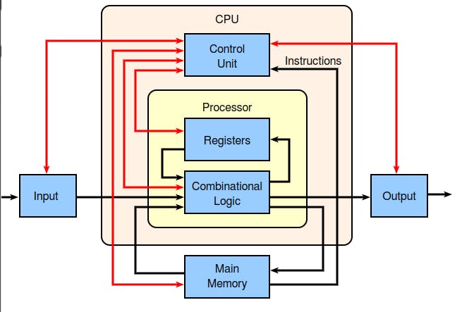
The next component in the computer is what we call the Central Processing Unit which basically contains both the ALU, register, and Control unit and also the Instruction decoder. ALU is for arithmetic operations, the register is a temporary component for storing data during operations. Both the control units are in charge of controlling what goes into the ALU and how machine code is being converted to instructions.
Here's a slightly refined version for better flow and clarity:
Note: The combinational logic encompasses all the components inside the ALU, while the others are referred to as Sequential logic.
RAM (Random Access Memory) and ROM (Read-Only Memory).
RAM: RAM serves as the primary memory of the computer, storing data and applications currently in use. It operates swiftly for both reading and writing data. It's essential to note that all data is lost once power is removed.
ROM: In contrast, ROM is stable, retaining data even in the absence of power. It is commonly used to store BIOS (Basic Input/Output System), providing instructions to the processor on resource access during startup. Unlike RAM, ROM is non-volatile.
A common misconception is using "ROM" to refer to hard disks (HDD or SSD). The correct terminology should be "500GB SSD memory" or similar, not "500GB ROM." Both RAM and ROM contain multiple registers.
Von Neumann Architecture - The Whole Computer: This leads us to the concept of stored programs, a principle introduced by Von Neumann. The idea is to separate the CPU from memory, retrieving data from memory and passing it through the bus for the CPU to execute instructions. This process follows the CPU cycle: fetch, decode, and execute.
The Von Neumann architecture comprises three main components: the CPU, I/O, and memory. Constructing this architecture is relatively straightforward, as we already have all the necessary components; they just need to be integrated.

In computer systems, Input and Output are conceptually treated as if they were part of the memory, a concept commonly referred to as memory mapping. When you input data through your keyboard, it's as if the CPU is accessing instructions via the bus from the memory. Subsequently, the CPU takes the necessary actions to execute these instructions.
Displayed below is an 8-bit Architecture originally designed by Uopeople, with a few modifications from my end. A closer look reveals some of the components we've explored in this blog.
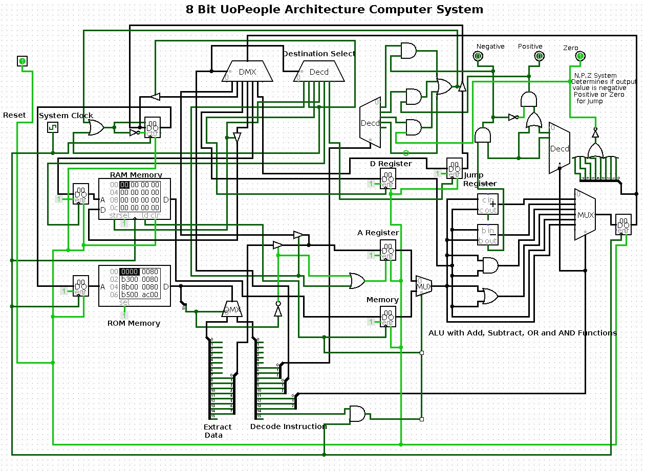
Conclusion.
With all this, we can definitely go on to create different operations to run machine code on our computer. Assembly language is basically a mapping of machine code to easily understandable language using an assembler.
There are lot of other things that I did not made mention in this blog. But, this give an overview of a computer architecture.
Image credit :- University of the People, Wikipedia, Research gate and myself.
